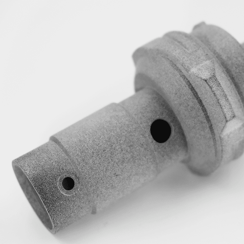
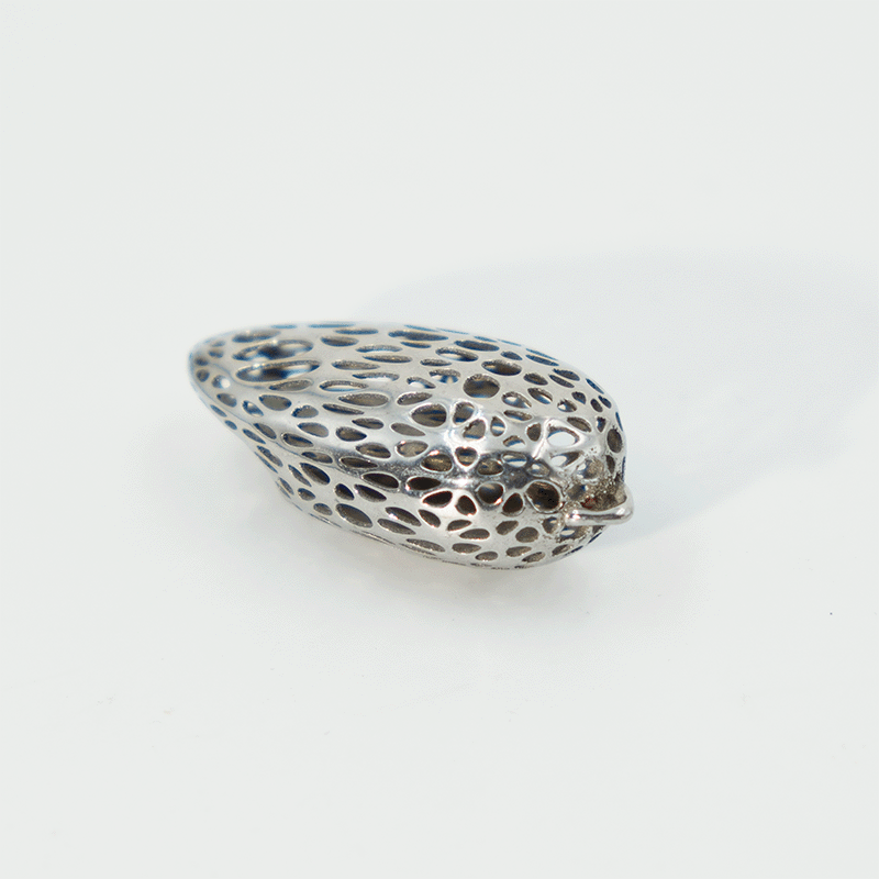
Scanning the metal powder bed with laser light, the powder will be melted and solidified into metal parts. The density of standard metal parts printed by SLM is over 99%, while the mechanical properties of SLM printed parts are as good as those manufactured by traditional processes. Moreover, parts with complex structures or parts that need to be lightweight designed can be easily manufactured with SLM.
|
Maximum build size |
Standard lead time |
Dimensional accuracy |
Layer height |
Minimum feature size |
|
420 × 420 × 450 mm |
From 5 business days |
± 0.2% with a lower limit of ± 0.2 mm (± 0.00787 in) |
50μm |
0.8 mm |
Leading companies across many industries use SLM for its industrial-grade materials
|
Material |
Color |
Resolution |
Tensile strength |
Elongation at break |
Heat deflection temperature |
Application |
|
AlSi10Mg |
Gray |
50μm |
330 MPa |
6 % |
660 °C |
Lightweight parts,Thermal properties parts |
|
SS316L |
Gray |
50μ |
560MPa |
10-20 % |
1200-1300 °C |
Corrosion resistance parts |
|
TC4 |
Gray |
50μ |
1000MPa |
4-10% |
1660-1680 °C |
Aviation,Medical |
|
MS1 |
Gray |
50μ |
1090MPa |
10% |
1300°C |
Injection mold |
|
|
Materials |
Price |
Dimensional accuracy |
Strengths |
Build volume |
Layer thickness |
Min. feature size |
|
FDM |
2 |
$ |
± 0.5% with a lower limit on ± 0.5 mm |
Low cost, wide range of materials |
500 x 500 x 500 mm (19.68" x 19.68" x 19.68") |
100-300μm |
2.0 mm (0.0787’') |
|
Industrial FDM |
6 |
$$$ |
± 0.3% with a lower limit of ± 0.3 mm (± 0.012") |
High level of repeatability, engineering grade materials |
914 x 610 x 914 mm (35.98” x 24.01” x 35.98") |
100-330μm |
2.0 mm (0.0787”) |
|
Industrial SLA |
3 |
$ |
± 0.2% with a lower limit of ± 0.13 mm (± 0.005") |
Smooth surface finish, fine feature details, big print area |
1000 x 1000 x 600 mm (39.37" x 39.37" x 23.62") |
50-100μm |
0.5 mm (0.00196”) |
|
SLS |
2 |
$$ |
± 0.3% with a lower limit of ± 0.3 mm (± 0.012”) |
Design flexibility, supports not required |
680 x 380 x 550 mm (26.77" x 14.96" x 21.65") |
100μm |
0.8 mm (0.0314”) |
|
MJF |
5 |
$$ |
± 0.3% with a lower limit on ± 0.3 mm (0.012’') |
Design flexibility, supports not required |
380 x 285 x 380 mm (14.9" x 11.2" x 14.9" ) |
80μm |
0.5 mm (0.0196”) |
|
SLM |
3 |
$$$ |
± 0.2% with a lower limit of ± 0.2 mm (± 0.00787 in) |
Produces a variety of metal material parts with high strength and high temperature resistance |
420 × 420 × 450 mm(16.54" x16.54" x17.72" ) |
50μm |
0.8 mm(0.0314) |
When printing process is finished, the printed parts are surrounded by un-melted metal powders, which means it is necessary to separate the printed parts from the un-melted powders and remove the condensates and bigger semi-melted particles. This process is called part unloading that can be done either manually on the machine or through a vacuum powder conveyor module which prevents direct contact from the powder.
The process of depowdering is to remove remaining trapped metal powder in the printed parts, which mechanical vibration can push the powder out of the printed parts. In such parts, any residual powder in the parts will hinder its functions. Additionally, if the part is heat treated without depowdering, the powder will be solidified, resulting in blocking the channels.
Heat treatment/ annealing is performed in a vacuum/ inert furnace. The heat treatment cycle is set according to the chemical composition of the material. Heat treatment reduces the internal thermal stress that occurs during printing and improves the mechanical properties of the printed parts. It is important to note that heat treatment is performed before separating the part from the build plate to avoid warping.
After finishing heat treatment process, it’s time to cut off the printed parts from the build plate. There are mainly three ways to deal with the cut-off process, which depends on the parts structures and supports.
1. Manual Chiselling
When the supports of printed parts are weak and minimal, chiselling out the supports can be applied.
2. Bandsaw
Bandsaw cutting requires printing about 5mm of additional material to compensate for blade thickness, which means it will increase the cost if printing large volume materials. Also, bandsaw is not precision cutting. Therefore, the cut surface must be machined for a better surface finish.
3. Wire EDM
As the easiest and most precise method of cut-off, the cut-off line is only 0.2mm diameter, and extra material with a thickness of only 0.25mm needs to be printed to compensate for the wire diameter.
By separating the printed parts from the build plate, it is easier to remove remaining supports on the parts.
1. Manual chiselling is the common way to remove supports. However, the surface finish of the support-removing area needs to be improved if using manual chiselling.
2. For surfaces with underlying supports that require a 2D profile with a good surface finish, using Wire EDM to remove supports is recommended.
3. For complex surfaces with supports beneath and requiring good surface finish, using CNC machining to remove supports is recommended.
Printed parts may require machining such as thread for fastening, holes for mounting a shaft, or a flat surface for butting. Part-specific Jigs and Fixtures are manufactured to clamp the part if needed.
Select the surface treatment technique by the desired type of finish and aesthetic appearance. Surface treatment technique includes vibro tumbling, shot blasting, abrasive flow machining, plating, polishing and micro machining.
8Inspection
The final stage of post-processing is inspection. There are three types of inspection applied.
1.CMM. Utilize CMM to make sure the dimensions are meeting the GD&T of the 2D drawings, and CMM report can be released if needed.
2. Mechanical inspection. Testing through laser scanning to ensure that the mechanical properties such as tensile, shear, microstructure, density and hardness is meeting the material datasheet.
3. Structural inspection. Using tests such as dye penetrant inspection, ultrasonic testing and CT scanning to ensure that the printed parts are free from surface cracks or porosity.
Copyright © 2021