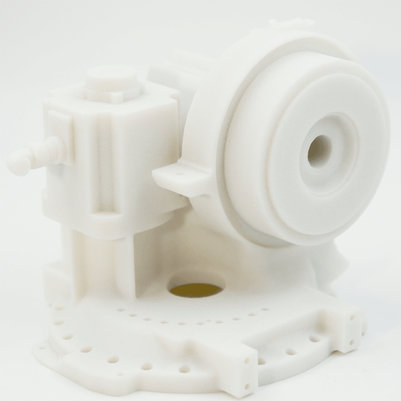
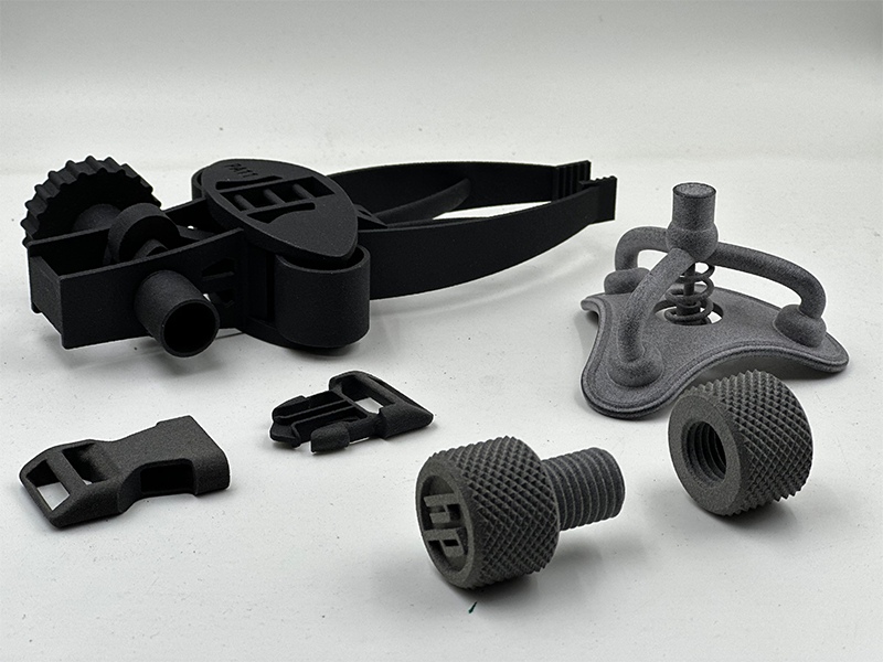
Multi Jet Fusion (MJF) is an advanced 3D printing process that can speedily produce accurate, complex and detailed parts from powdered thermoplastics. MJF parts have high tensile strength and fine feature resolution, making them perfect for complex industrial parts. Developed by HP, this relatively new 3D printing technology is perfect for creating functional prototyping and production parts with isotropic mechanical properties, making it a go-to for any application requiring geometric complexity and impressive cosmetic and mechanical properties.
|
Maximum build size |
Standard lead time |
Dimensional accuracy |
Layer height |
Minimum feature size |
|
380 × 284 × 380 mm |
From 1 business days |
± 0.3% with a lower limit of ± 0.3 mm (± 0.012 in) |
80μm |
0.5 mm |
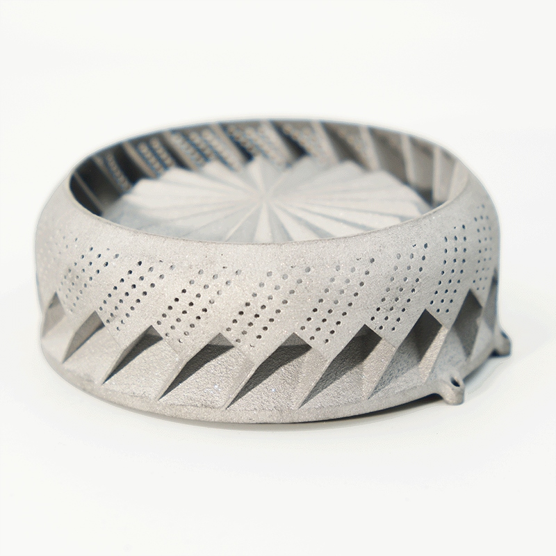
Leading companies across many industries use MJF for its industrial-grade materials
|
Material |
Color |
Resolution |
Tensile strength |
Elongation at break |
Heat deflection temperature |
Application |
|
HP PA 12 (Nylon 12) |
Gray, dyed black |
80μm |
48 MPa |
15-20 % |
95-175 °C |
Functional prototypes, complex assemblies, watertight applications |
|
Glass-filled HP PA 12 |
Gray, dyed black |
80μm |
30 MPa |
6.5 % |
121-173 °C |
Enclosures, housings, cases, fixtures, structural parts, tooling |
|
HP PA 11(Nylon 11) |
Gray, dyed black |
80μm |
54 MPa |
40% |
54-185 °C |
prostheses, insoles, sports goods, snap fits, living hinges |
|
BASF TPU |
Gray, dyed black |
80μm |
9MPa |
310% |
84°C |
Wearable devices, tooling fixtures, hoses, shoe midsoles, lattice structures |
|
BASF PP |
Gray, dyed black |
80μm |
29MPa |
20% |
60-100°C |
Corrosion-resistant,watertight applications, oil tank |
|
|
Materials |
Price |
Dimensional accuracy |
Strengths |
Build volume |
Layer thickness |
Min. feature size |
|
FDM |
2 |
$ |
± 0.5% with a lower limit on ± 0.5 mm |
Low cost, wide range of materials |
500 x 500 x 500 mm (19.68" x 19.68" x 19.68") |
100-300μm |
2.0 mm (0.0787’') |
|
Industrial FDM |
6 |
$$$ |
± 0.3% with a lower limit of ± 0.3 mm (± 0.012") |
High level of repeatability, engineering grade materials |
914 x 610 x 914 mm (35.98” x 24.01” x 35.98") |
100-330μm |
2.0 mm (0.0787”) |
|
Industrial SLA |
3 |
$ |
± 0.2% with a lower limit of ± 0.13 mm (± 0.005") |
Smooth surface finish, fine feature details, big print area |
1000 x 1000 x 600 mm (39.37" x 39.37" x 23.62") |
50-100μm |
0.5 mm (0.00196”) |
|
SLS |
2 |
$$ |
± 0.3% with a lower limit of ± 0.3 mm (± 0.012”) |
Design flexibility, supports not required |
680 x 380 x 550 mm (26.77" x 14.96" x 21.65") |
100μm |
0.8 mm (0.0314”) |
|
MJF |
5 |
$$ |
± 0.3% with a lower limit on ± 0.3 mm (0.012’') |
Design flexibility, supports not required |
380 x 285 x 380 mm (14.9" x 11.2" x 14.9" ) |
80μm |
0.5 mm (0.0196”) |
|
SLM |
3 |
$$$ |
± 0.2% with a lower limit of ± 0.2 mm (± 0.00787 in) |
Produces a variety of metal material parts with high strength and high temperature resistance |
420 × 420 × 450 mm(16.54" x16.54" x17.72" ) |
50μm |
0.8 mm(0.0314) |
This takes place within the build unit, though HP offers module units for natural cooling, so the build unit can be used for a new print without having to wait for the powder and part to cool.
Once the build unit has cooled down, move it to the processing station and vacuum the unfused powder into a container for later use.
Remove any remaining powder with bead blasting, air blasting or water blasting. You can do this manually or automatically, using a tumbler, ultrasonic cleaner or vibratory finishing machine.
You can choose to dye your printed parts black. The dyeing temperature is about 90°C.
Copyright © 2021